GRDECL grids
The GRDECL conventions and the supported keywords are described below:
Conventions within Grdecl input files
Within a GRDECL file the data syntax and conventions are those of Eclipse rather than Cirrus, in the following respects:
The data is placed on a new line, after the keyword. The values are normally delimited by spaces (although tabs are accepted), and may be split across a number of lines. Data will be read until either the correct number of items have been processed, or a / terminating character is encountered. If all the expected values are present, a / character may still be added and will do no harm.
Repeat counts may be used – for example, 3000*0.44 implies 3000 values of 0.44.
Defaults may be used – for example, 3000* implies 3000 default values. For
MULTX, for example the default value is 1.0, so 5* would be the same as 5*1.0 which would be the same as 1.0 1.0 1.0 1.0 1.0.Depths are measured downwards.
Permabilities are measured in milliDarcies (mD)
The basic ordering scheme is natural ordering – with the I-index changing fastest, then the J-index, and with the K-index changing slowest. The K-order is down the columns of cells.
DIMENS
This keyword sets the basic dimensions of the (I,J,K) grid, the three arguments being Nx, Ny, and Nz. The following example specifies a 130 by 187 by 34 grid.
DIMENS
130 187 34 /
FIELD
Specifies the use of field units.
If this keyword is found, field units are assumed for data entered in the .grdecl file. By default units are assumed to be metric. Example:
FIELD
METRIC
Specifies the use of metric units.
If this keyword is found, metric units are assumed for data entered in the .grdecl include file. By default units are assumed to be metric. Example:
METRIC
FIELD_US/FIELD_USA
This keyword applies to a grdecl file, usually introduced using the TYPE keyword in the GRID block:
GRID
  TYPE grdecl base.grdecl
END
Within that file (base.grdecl in the above example), the units (for that file only) can be set using FIELD, METRIC, or FIELD_US (alias FIELD_USA) keywords. Example:
FIELD_US
FIELD_US is needed because the USA definition of the unit of a foot differs very slightly from the international unit of a foot, assumed by default when the FIELD unit system is requested. Internally, Cirrus works in metres.
When using FIELD, the conversion from international feet to metres is:
convdist = 0.3048
When using FIELD_US the conversion from USA feet is:
convdist = 0.3048/0.999998
Note both conversions are exact.
It is common to introduce further files with the INCLUDE keyword, such as those written out by pre-processors such as Petrel © and IRAP/RMS ©. In those include files, a new unit system can be set up, which will overwrite what specified in the parent .grdecl file.
Note that if an include file containing the Eclipse MAPUNITS keyword is used (MAPUNITS specify ‘FEET’ or ‘METRES’) then USA feet will be used if FIELD_US has been requested before reading the include file.
This keyword only affects distance information read in the grdecl file. Quantities such as wellbore diameters in the WELL_DATA section will still be read in the specified units, and if the units are feet they will be international feet.
This keyword has no arguments.
COORD
This keyword, combined wth ZCORN, allows a grid with dip and displacement faults to be
entered. COORD consists of \((N_x+1)(N_y+1)\) sets of ‘coordinate lines’ each specified by a lower and an upper point, each of which is defined by an x,y,z triplet.
In almost every case, COORD/ZCORN data is produced by a pre-processor. However, here is
a very simple example, which could be used to set up a 1x1x2 cell grid. It defines cells with
an areal extent of 10m by 10m:
COORD
0  0  0 0  0  10000
10 0  0 10 0  10000
0  10 0 0  10 10000
10 10 0 10 10 10000
/
ZCORN
This keyword specifies the depth of each cell node in the grid defined by DIMENS and
COORD. As mentioned under COORD, COORD/ZCORN data is usually generated by a pre-processor. However, here is an example for the 1x1x2 grid considered in the COORD
example above:
ZCORN
4*2003 8*2015 4*2032 /
Note that there are 8*Nx*Ny*Nz depths present, setting the four top corner depths of the
top cell to 2003 m, the four corners at the bottom of the top cell to 2015, the four corners
of the top of the bottom cell to 2015 m and the four corners at the bottom of the bottom
cell to 2032 m.
It is important to be aware that the arguments of ZCORN are depths, as positive numbers
measured downwards.
It would be common to include a file of COORD/ZCORN data using EXTERNAL_FILE, as in:
EXTERNAL_FILE gridgeo/geometry_a.grdecl
Units: note that the units of ZCORN are always meters unless GRIDUNITS has selected feet.
DX
To enter a simple regular grid, DX, DY and DZ may be used. This is an alternative to
COORD/ZCORN. This keyword specifies the dimension of each cell in the grid x-direction. It
is very common to enter this data with a repeat count, such as:
DX
1122000*6.096
Units: the units of DX are always meters unless GRIDUNITS has selected feet.
Note that the order of values is the GRDECL default natural order, with the x-index
changing fastest, the z-index changing most slowly, starting from the top layer of the
reservoir.
DY
This keyword specifies the dimension of each cell in the grid y-direction. It is analogous to
DX.
Units: the units of DY are always meters unless GRIDUNITS has selected feet.
Note that the order of values is the GRDECL default natural order.
DZ
This keyword specifies the dimension of each cell in the grid z-direction. It is analogous to
DX and DY. As reservoirs commonly have a different thickness for each layer, it is common
to enter repeated values by layer, for example, for a 10x10x3 grid:
DZ
100*6.096 100*9.144 100*15.24 /
Units: the units of DZ are always meters unless GRIDUNITS has selected feet.
Note that the order of values is the GRDECL default natural order.
Note that the layers count down from the top layer.
Note that the terminating / character is not required if a full set of values has been entered.
PERMX
Specify the permeability for each cell in the grid in the x-direction.
An example is for a 10x10x3 grid, in which the top layer has an x-permeability of 50 mD, the middle layer has a permeability of 50 mD and the bottom layer has a permeability of 200 mD.
PERMX
100*500.0 100*50.0 100*200.0
Units are mD.
Default: The default is 0.
Note that the order of values is the GRDECL default natural order.
Note that in the above example a full set of \(N_x N_y N_z\) values has been provided, so the terminating / character is not required (although it may be added). If the terminator is used before all the values have been entered, the remaining values will be set to the default of zero.
PERMY
Specify the permeability for each cell in the grid in the y-direction. This keyword is
analogous to PERMX.
Units are mD.
Default: The default is 0.
PERMZ
Specify the permeability for each cell in the grid in the z-direction.
analogous to PERMX.
Units are mD.
Default: The default is 0.
MULTV
Specify the volume multipliers for each cell in the grid. The default is 1.0
The volume multiplier acts on the pore volume and the bulk volume of a cell (so that the amount of fluid and the rock thermal capacity are increased by the same factor). Example, where we duplicate the volume:
MULTV
  300*2.0 /
MULTX
Specify the x-direction transmissibility multipliers for each cell in the grid. The default is 1.0
The x-direction transmissibility multiplier acts on the flow between a cell and its x-direction
neighbour in the positive direction. So a MULTX value of 0.5 for cell (1,1,1) in a regular grid
would halve the transmissibility between cell (1,1,1) and (2,1,1).
MULTY
Specify the y-direction transmissibility multipliers for each cell in the grid. The default is 1.0
The y-direction transmissibility multiplier acts on the flow between a cell and its y-direction
neighbour in the positive direction. So a MULTY value of 0.5 for cell (1,1,1) in a regular grid
would halve the transmissibility between cell (1,1,1) and (1,2,1).
MULTZ
Specify the z-direction transmissibility multipliers for each cell in the grid. The default is 1.0
The z-direction transmissibility multiplier acts on the flow between a cell and its z-direction
neighbour in the positive z-direction (that is, its downwards neighbour). So a MULTZ value of
0.5 for cell (1,1,1) in a regular grid would halve the transmissibility between cell (1,1,1) and
(1,1,2).
As an example, for a 100x100x10 grid, the following MULTZ data would prevent flow between the 6 th and 7 th layers, counting from the top:
MULTZ
50000*1.0 10000*0.0 40000*1.0 /
MULTX-
Specify negative x-direction transmissibility multipliers for each cell in the grid. The default is 1.0
The negative x-direction transmissibility multiplier acts on the flow between a cell and its x-direction neighbour in the negative direction. So a MULTX- value of 0.5 for cell (3,1,1) in a regular grid would halve the transmissibility between cell (3,1,1) and (2,1,1).
MULTY-
Specify negative y-direction transmissibility multipliers for each cell in the grid. The default is 1.0
The negative y-direction transmissibility multiplier acts on the flow between a cell and its y-direction neighbour in the negative direction. So a MULTY- value of 0.5 for cell (1,3,1) in a regular grid would halve the transmissibility between cell (1,3,1) and (1,2,1).
MULTZ-
Specify negative z-direction transmissibility multipliers for each cell in the grid. The default is 1.0
The negative z-direction transmissibility multiplier acts on the flow between a cell and its z-direction neighbour in the negative z-direction (that is, its upwards neighbour). So a MULTZ- value of 0.5 for cell (1,1,3) in a regular grid would halve the transmissibility between cell (1,1,3) and (1,1,2).
TRANX
Overwrites the transmissibilities in the X-direction computed internally by the code. The values must be entered in the GRDECL default natural order. Only non-negative entries are accepted.
It applies to the I+ direction, for example a value entered for the block (I,J,K), is the transmissibility between the (I,J,K) and (I+1,J,K) blocks.
Units are cP.m3/day/bar.
Below an example for a model with 100 grid blocks:
TRANX
100*40.5 /
TRANY
Overwrites the transmissibilities in the Y-direction computed internally by the code. The values must be entered in the GRDECL default natural order. Only non-negative entries are accepted.
It applies to the J+ direction, for example a value entered for the block (I,J,K), is the transmissibility between the (I,J,K) and (I,J+1,K) blocks.
Units are cP.m3/day/bar.
TRANZ
Overwrites the transmissibilities in the Z-direction computed internally by the code. The values must be entered in the GRDECL default natural order. Only non-negative entries are accepted.
It applies to the K+ direction, for example a value entered for the block (I,J,K), is the transmissibility between the (I,J,K) and (I,J,K+1) blocks.
Units are cP.m3/day/bar.
PORO
Specify the rock porosities as fractions.
The default is 0.0.
When a cell is given a zero porosity, it will be made inactive and excluded from the simulation. An example is a 100x100x10 grid, with the entire 5 th layer being removed and made inactive:
PORO
40000*0.35 10000*0.0 50000*0.23 /
TOPS
Specify the cell top depth. Normally, only the top layer need be specified, and cells below
the top layer will be placed underneath that layer at depths which honor the DZ values of
the cells. However, it is possible to specify the TOPS depths of all the cells. If this results in
the cells being separated in space, then it is possible that the gap between two cells would
result in a zero flow between them. The separation required to cause such a zeroing of the
flow is controlled by the PINCH keyword.
Units: the units of TOPS are always meters unless GRIDUNITS has selected feet.
Example:
TOPS
1900 /
/
NTG
Specify the net-to-gross ratios as fractions. The default is 1.0.
Net-to-gross ratios represent the fraction of the material in a cell which has the given porosity value. The remaining fraction is assumed to have zero porosity and permeability. It is also assumed that the impermeable material is arranged in layers. The NTG fraction is applied to the pore volume and to permeabilities for flows in the x and y directions.
Note that the material which is not in the NTG fraction is assumed to play no role in the
simulation. In a thermal simulation in which heat may conduct into impermeable rock, it
may be better to include the NTG value in the porosity, and set the rock properties to
reflect those of both the rock in the porous fraction and the rock in the non-porous fraction
of the cell.
Note that the order of values is the GRDECL default natural order. Example:
MULTV
        300*0.9 /
NTOG
Alias of NTG.
ACTNUM
Specify the active cell status for each cell. \(N_x N_y N_z\) integer values are expected, which should each be 0, 1, 2 or 3, the default being 1. The order of values is the GRDECL default natural order.
A value of 0 will render the cell inactive.
A value of 1 implies that the cell is active, subject to the
MINPVcriterion.A value of 2 will set the porosity to 0.000001, so that the cell is rock-filled, which can be useful in some thermal runs.
A value of 3 will set the pore volume to the bulk volume (i.e. porosity of 100%).
Example:
ACTNUM
  300*2 /
ACTNUM is also commonly used within EQUALS to disable sections. Example:
EQUALS
 ACTNUM 0 7 7 15 15 1 1
 ACTNUM 0 30 30 29 29 12 12
/
SATNUM
Specify the set of CHARACTERISTIC_CURVES to be used for each cell.
\(N_x N_y N_z\) integer values are expected, which should each be in the range \(1\) to \(N_{cc}\), where \(N_{cc}\) is the number of sets of CHARACTERISTIC_CURVES provided. The order of values is the GRDECL default natural order.
An example is given below:
SATNUM
300*1  /
A set of saturation table function is normally supplied, each one enclosed by the CHARACTERISTIC_CURVES block. The sets of saturation table functions are assigned numbers based on the order in which they appear in the input data – the names under CHARACTERISTIC_CURVES are not used. Sets of saturation functions are then assigned to cells using the SATNUM grid array.
IMBNUM
Specify the set of CHARACTERISTIC_CURVES to be used for imbibition processes.
\(N_x N_y N_z\) integer values are expected, which should each be in the range \(1\) to \(N_{cc}\), where \(N_{cc}\) is the number of sets of CHARACTERISTIC_CURVES provided. The order of values is the GRDECL default natural order.
An example is given below:
IMBNUM
300*2  /
A set of saturation table function is normally supplied, each one enclosed by the CHARACTERISTIC_CURVES block. The sets of saturation table functions are assigned numbers based on the order in which they appear in the input data – the names under CHARACTERISTIC_CURVES are not used. Sets of saturation functions are then assigned to cells using the IMBNUM grid array.
KRNUMX, KRNUMY, KRNUMZ
Specifies the set of CHARACTERISTIC_CURVES (saturation functions) to be used for each cell in the X, Y and Z directions (directional relative permeabilities).
\(N_x N_y N_z\) integer values are expected, which should each be in the range \(1\) to \(N_{cc}\), where \(N_{cc}\) is the number of sets of CHARACTERISTIC_CURVES provided. The order of values is the
GRDECL default natural order.
An example is given below:
KRNUMX
200*2 /
A set of saturation table functions is normally supplied, each one enclosed by the
CHARACTERISTIC_CURVES block. The sets of saturation table functions are assigned numbers based
on the order in which they appear in the input data – the names under CHARACTERISTIC_CURVES are not used. Sets of saturation functions for the X, Y and Z directions are then assigned to cells using the KRNUMX, KRNUMY and KRNUMZ grid arrays. In the absence of directional relative
permeabilities the same saturation functions are used for flow in any direction. Directional relative
permeabilities will be used if KRNUMX, KRNUMY, KRNUMZ are found.
For more details, see Directional Relative Permeability.
IMBNUMX, IMBNUMY, IMBNUMZ
Specifies the set of CHARACTERISTIC_CURVES (saturation functions) to be used for each cell in the X, Y and Z directions for imbibition processes (directional relative permeabilities).
\(N_x N_y N_z\) integer values are expected, which should each be in the range \(1\) to \(N_{cc}\), where \(N_{cc}\) is the number of sets of CHARACTERISTIC_CURVES provided. The order of values is the GRDECL default natural order.
An example is given below:
IMBNUMX
200*3  /
A set of saturation table functions is normally supplied, each one enclosed by the
CHARACTERISTIC_CURVES block. The sets of saturation table functions are assigned numbers based
on the order in which they appear in the input data – the names under CHARACTERISTIC_CURVES are not used. Sets of saturation functions for the imbibition process in X, Y and Z directions are then
assigned to cells using the IMBNUMX, IMBNUMY and IMBNUMZ grid arrays. In the absence of
directional relative permeabilities the same saturation functions are used for flow in any direction.
Directional relative permeabilities will be used for imbibition if IMBNUMX, IMBNUMY, IMBNUMZ are found.
For more details, see Directional Relative Permeability.
MINPV
Set the criteria for a cell to be made inactive on the basis of a low or zero pore volume. This keyword takes a single argument, the pore volume below which a cell is deemed to be inactive and excluded from the simulation. The default value is 0.001 rm^3 (reservoir cubic meters). Larger values can be used to exclude cells with small volumes which may create problems for the simulator.
An example is:
MINPV
1000 /
This will exclude any cell with a pore volume of less than 1000 rm^3 from the simulation.
MINDZ
This keyword is like MINPV, except that it makes a cell inactive if it has a thickness (DZ) value below the specified minimum value. An example of the usage is:
mindz -- Make layers with dz<0.001 inactive
0.001 /
PINCH
Define how pinch-outs (inactive layers between active cells) are to be handled. This keyword takes a single value, which is the maximum distance between two cells in non- neighboring layers with intervening inactive cells, such that a pinch-out connection will be generated between them. The separation distance is the largest of the four corner separation distances. If this separation distance exceeds the pinch-out distance no connection will be generated.
An example is:
PINCH
0.1 /
The default value is 0.001 meters.
Units: the units of PINCH are always meters unless GRIDUNITS has selected feet.
NEWTRAN
Use a transmissibility calculation which allows displacement faults. This is the default for
COORD/ZCORN.
OLDTRAN
Use a transmissibility calculation which only connects neighbors in the IJK grid. This is the
default for DX/DY/DZ.
DPCF
Generates a heterogeneous permeability distribution using a Dystra-Parsons standard distribution in ln(K) around the user-specified values. An example is given below:
dpcf
0.3  1 /
The first argument is the Dykstra-Parsons coefficient [DP50], which is the reservoir heterogeneity index (\(\mbox{RHI}\)). The range of this index is between 0 and 1:
\(\mbox{RHI} = 0\) |
Homogenous reservoir |
\(0.0 < \mbox{RHI} < 0.25\) |
Slightly heterogeneous reservoir |
\(0.25 < \mbox{RHI} < 0.5\) |
Heterogeneous reservoir |
\(0.5 < \mbox{RHI} < 0.75\) |
Very heterogeneous reservoir |
\(0.75 < \mbox{RHI} < 1.0\) |
Extremely heterogeneous reservoir |
\(\mbox{RHI} = 1\) |
Perfectly heterogeneous reservoir; unlikely this exists in reality |
The second optional argument is the integer random number seed value. The default, 0 or 1 will all give the same pseudo-random sequence (i.e. the same consistent heterogeneity will be obtained in successive runs). Positive values 2, 3, 4 etc. will give different pseudo-random sequences.
The \(DPCF\) option introduces heterogeneity generating relative permeabilities that are not correlated and not representative of any real field. In general, larger values of \(\mbox{RHI}\) make the problem harder to solve, especially for values above 0.5.
ADD
Define an addition to a grid quantity in some box of cells in the I,J,K grid. This is the first of
a set of four keywords (ADD, COPY, EQUALS and MULTIPLY) which allow changes to be made
to the grid data.
The syntax is typically as in the example below:
ADD
<grid array name1> <value1> <il1 iu1 jl1 ju1 kl1 ku1> /
<grid array name2> <value2> <il2 iu2 jl2 ju2 kl2 ku2> /
...
/
where <grid array name> values are one of the set:
dx,dy,dz, permx,permy,permz, multx,multy,multz, poro, tops, ntg, actnum, satnum
<value> = value to be added to the grid array
<il iu jl ju kl ku> = box of cells in Cartesian indexing space which selects the cells to which the operation applies. If these values are omitted the initial default the entire reservoir. If entered, the operation applies to cells with coordinates i,j,k such that \(il\leq i\leq iu\); \(jl\leq j\leq ju\) and \(kl\leq k\leq ku\).
When a series of operations is defined under a single ADD keyword, the default of cell limits for each record are the values used in the previous record.
il,jl and kl default to 1, iu defaults to Nx, ju defaults to Ny and ku defaults to Nz.
The list of addition operations is terminated when a null record (just a / character on a new line) is encountered.
An example is an addition to the permeability in the region \(1\leq I\leq 45\), \(8\leq J\leq 67\), \(15\leq K\leq 16\):
ADD
PERMX 105.2 1 45 8 67 15 16 /
/
Note that the BOX is defined using the GRDECL convention that layers are counted down
from the top of the reservoir.
COPY
Copy the contents of one grid array to another in some box of cells.
The syntax is typically:
COPY
<from_grid array name1> <to_grid array name1> <il1 iu1 jl1 ju1 kl1 ku1> /
<from_grid array name2> <to_grid array name2> <il2 iu2 jl2 ju2 kl2 ku2> /
...
/
where <from_grid array name> and <to_grid array name> are both from the set dx,dy,dz, permx,permy,permz, multx,multy,multz, poro, tops, ntg, actnum, satnum.
The limits of the operation are defined by the box of coordinate limits <il iu jl ju kl ku> in the same way as for the ADD keyword.
A common example of the use of COPY is setting the PERMY values equal to the PERMX values:
COPY
PERMX PERMY /
/
EQUALS
Set the contents of a grid array to a value in some box of cells. The syntax is typically:
EQUALS
<grid array name1> <value1> <il1 iu1 jl1 ju1 kl1 ku1> /
<grid array name2> <value2> <il2 iu2 jl2 ju2 kl2 ku2> /
...
/
where <grid array name> is one of the set: dx,dy,dz, permx,permy,permz, multx,multy,multz, poro, tops, ntg, actnum, satnum, tranx, trany, or tranz.
<value> is the value to be assigned to the grid array
The limits of the operation are defined by the box of coordinate limits <il iu jl ju kl ku> in the same way as for the ADD keyword.
A common usage of the EQUALS keyword is to assign a single value to an array over the whole reservoir:
EQUALS
  DX    50.0 /
  DY    50.0 /
  DZ    5.0 /
  PORO  0.2 /
  PERMX 100.0 /
/
MULTIPLY
Multiply the values of a grid quantity in some box of cells. The syntax is typically:
MULTIPLY
<grid array name1> <value1> <il1 iu1 jl1 ju1 kl1 ku1> /
<grid array name2> <value2> <il2 iu2 jl2 ju2 kl2 ku2> /
...
/
Where <grid array name> is one of the set:
dx,dy,dz, permx,permy,permz, multx,multy,multz, poro, tops, ntg, actnum, satnum;
or of the set:
porv, tranx, trany, tranz.
<value> is the value by which the grid array is to be multiplied
The limits of the operation are defined by the box of coordinate limits <il iu jl ju kl ku> in the same way as for the ADD keyword.
A common usage of the MULTIPLY keyword is to multiply an array over the whole reservoir:
MULTIPLY
PERMZ 0.2 /
/
Internally, PORV multiplication is applied to PORO, and TRANX multiplications are applied to MULTX etc.
OPERATE
Operate is a keyword like ADD, COPY or MULT, but which allows a number of more complex operations to be carried out.
The keyword follows a standard pattern with a series of records being terminated by a null record, and each one has up to 11 argument values. The first value is the name of an array to be operated on, and values 2 to 7 are a box of limits to the operation in IJK space.
The 8th argument defines the type of operation to be performed, whilst the last three arguments are one array name and two scalar possible values to be used in the operation:
OPERATE
y1 ixl1 ixu1 iyl1 iyu1 izl1 izu1 operation1 x1 a1 b1 /
y2 ixl2 ixu2 iyl2 iyu2 izl2 izu2 operation2 x2 a2 b2 /
...
yn ixln ixun iyln iyun izln izun operationn xn an bn /
/
The target array y may or may not be the same as the input array x.
Not all the arguments are used in all the operations.
The operations supported are:
1 |
|
\(y = ax + b\) |
2 |
|
\(y = xy\) |
3 |
|
\(y = \min(x,a)\) |
4 |
|
\(y = \max(x,a)\) |
5 |
|
\(y = \log_{10}(x)\) |
6 |
|
\(y = \log_e (x)\) |
7 |
|
\(y = \|x\|\) |
8 |
|
\(y = 1/x\) |
9 |
|
\(y = xa\) |
10 |
|
\(y = x + a\) |
11 |
|
\(y = ax^b\) |
12 |
|
\(y = t + ax^b\) |
13 |
|
\(y = 10^{(a+bx)}\) |
14 |
|
\(y = x\) |
Examples of these operations can be found in the cirrus repository at regression_tests/towg/gw, cases op1.in to op14.in.
The actual OPERATE keywords are in the files op1.grdecl to op14.grdecl and take the form:
MULTA
(with PERMX = 100 and PERMZ = 100):
OPERATE
--             x     a b
PERMY 6* multa PERMX 2 50 / -- permy:= a.x + b = 2*permx + 50 = 250
PERMZ 6* multa PERMZ 3 60 / -- permz:= a.x + b = 3*permz + 60 = 360
/
MULTIPLY
(with MULTX = 2 and MULTY = 3):
OPERATE
multy 6* multiply multx / -- multy:= multx*multy = 2*3 = 6
MINLIM
(with multx = 2, permx = 100 mD):
OPERATE
--              x     a
multy 6* minlim multx 0.5 / -- multy = min(x,a) = min(2  ,0.5) = 0.5
permx 6* minlim permx 1.5 / -- permx = min(x,a) = min(100,1.5) = 1.5 mD
MAXLIM
(with multx = 2, permx = 100 mD):
OPERATE
--              x     a
multy 6* maxlim multx 2.5 / -- multy:=max(x,a) = max(2  ,2.5) = 2.5
permx 6* maxlim permx 250 / -- permx:=max(x,a) = max(100,250) = 250 mD
/
LOG10
(with multx = 100):
OPERATE
multy 6* log10 multx / multy:=log10(100)=2
LOGE
(with multx = 100):
OPERATE
multy 6* loge multx / -- multy:=loge(100)=4.605
ABS
(with multx set intially to -100):
multx 6* abs multx / -- multx:=abs(x) = abs(-100) = 100
INV
(with multx set to 100):
OPERATE
multx 6* inv multx / -- multx: = 1/x = 1/100 = 0.01
MULTX
(with PERMX = 100 mD):
OPERATE
--             x     a
permx 6* multx permx 2 / -- permx = a.x = 2*100 = 200 mD
ADDX
(with PERMX = 100 mD):
OPERATE
--            x     a
permx 6* addx permx 2 / -- permx := x + a = 100 + 2 = 102 mD
MULTP
(with MULTX = 10):
OPERATE
--             x     a b
multx 6* multp multx 3 2 / -- multx := a.x**b = 3.10**2 = 300
12 POLY
(with MULTX = 10):
OPERATE
--            x     a b
multx 6* poly multx 3 2 / -- multx:=x+a.x**b = 10 + 3*10**2 = 310
SLOG
(with MULTX = 4):
OPERATE
--            x     a b
multx 6* slog multx 2 0.25 / -- multx=10.0**(a+b.x)=10.0**(2+0.25*4)=10.0**3=1000
14. COPY
(with MULTX = 10):
OPERATE
multy 6* copy multx / --Copy multx value of 10 into the result multy
Notes:
Some power operations like loge cannot be applied to dimensionful quantities such as permeabilities.
Permeabilities are treated in OPERATE as being in units of mD
Is is possible to do repeated operations, such as:
OPERATE
permx 6* addx permx 2 / -- permx := permx + a = 100 + 2 = 102
permx 6* addx permx 2 / -- permx := permx + a = 100 + 2 = 104
permx 6* addx permx 2 / -- permx := permx + a = 100 + 2 = 106
/
OPERATER
OPERATER is a similar keyword to OPERATE. Like OPERATE, it is a keyword like ADD, COPY or MULT which acts on grid data, but which allows a number of more complex operations to be carried out.
The difference is that OPERATE acts on an set of cells defined by box of limits in IJK space, but OPERATER acts on cells with a given value of the OPERNUM keyword.
The form of the keyword is:
OPERATER
y1 ioprn1 operation1 x1 a1 b1 /
y2 ioprn2 operation2 x2 a2 b2 /
...
yn ioprnn operationn xn an bn /
/
The target array y may or may not be the same as the input array x. The usage of the input array and the parameters a and b is the same as in the OPERATE keyword.
Not all the arguments are used in all the operations.
The operations supported are:
1 |
|
\(y = ax + b\) |
2 |
|
\(y = xy\) |
3 |
|
\(y = \min(x,a)\) |
4 |
|
\(y = \max(x,a)\) |
5 |
|
\(y = \log_{10}(x)\) |
6 |
|
\(y = \log_e (x)\) |
7 |
|
\(y = \|x\|\) |
8 |
|
\(y = 1/x\) |
9 |
|
\(y = xa\) |
10 |
|
\(y = x + a\) |
11 |
|
\(y = ax^b\) |
12 |
|
\(y = t + ax^b\) |
13 |
|
\(y = 10^{(a+bx)}\) |
14 |
|
\(y = x\) |
Examples of these operations can be found in the cirrus repository at regression_tests/towg/gw, cases opn1.in to opn14.in.
The actual OPERATE keywords are in the files opn1.grdecl to opn14.grdecl and take the form, for example:
For MULTA operation:
(with PERMX=100 and PERMZ=100)

EQUALS
OPERNUM 2 4* 2 2 /
/

OPERATER
--             x     a b
PERMY 2 multa PERMX 2 50 / -- permy:= a.x + b = 2*permx + 50 = 250
PERMZ 2 multa PERMZ 3 60 / -- permz:= a.x + b = 3*permz + 60 = 360
/
In this the operation only acts on cells in the second layer.
Note that the OPERNUM array values should be set up before they are used in the OPERATE keyword.
For more examples, please see OPERATE, which works similarly.
OPERNUM
Specify a set of values to be used with the OPERATER keyword. \(N_x \cdot N_y \cdot N_z\) integer values are expectedThe order of values is the GRDECL default natural order.
An example is given below:
OPERNUM
100*1 100*2 100*1 /
An OPERATER keyword entered after this OPERNUM one might then chose to act only on cells with an OPERNUM index of 2.
FAULTS
Define the path of a barrier fault across the reservoir. This type of fault defines a transmissibility barrier in the reservoir.
FAULTS
‘FAULTA’ 1  5  6  6  1  10 Y /
‘FAULTA’ 5  5  6  8  1  10 X /
‘FAULTA’ 6 10  8  8  1  10 Y /
‘FAULTB’ 1 10  9  9  1  10 Y /
/
In each fault record the six integers define a box of cells, and the last value (which can be X, Y, Z, X-, Y- or Z-) defines a cell face.
In the case of X, Y or Z this is the ‘upper’ cell face in the GRDECL indexing convention – i.e., X implies from the cell to its positive x-index neighbour, Y implies from the cell to its positive y-index neighbour, and Z implies from the cell to the cell below it.
In the case of X-, Y- or Z- this is the ‘lower’ cell face in the GRDECL indexing convention – i.e., X- implies from the cell to its negative x-index neighbour, Y- implies from the cell to its negative y-index neighbour, and Z- implies from the cell to the cell above it.
Note that the X, Y and Z cases operate by making changes to the MULTX, MULTY and MULTZ transmissibility multiplier arrays, whilst the X-, Y- and Z- cases operate by making changes to the MULTX-, MULTY- and MULTZ- transmissibility arrays.
The series of fault records is teminated when an empty record (a single / character) is encountered.
Note: Quotes are accepted but are not required. The name can be up to 32 characters and case is not significant.
MULTFLT
Set the multiplier for a fault defined with FAULTS. This multiplier is applied to all the cell faces defined in the corresponding FAULTS track.
MULTFLT
FAULTA 0.5 /
FAULTB 0.0 / ! Sealing fault
/
Note: Quotes are accepted but are not required. The name can be up to 32 characters and case is not significant.
MULTNUM
This keyword is used to define regions to apply inter-region transmissibility multipliers. It is intended to be used in combination with MULTREGT. \(N_x \cdot N_y \cdot N_z\) integer values are expected, defining to which region each grid cell belongs to. For a 2x2x2 model with 5 regions we could do:
MULTNUM
 1 2 3 4 5 1 2 3
 /
Here, we have assigned cell 1 and 6 to region 1, 2 and 7 to region 2, 3 and 8 to region 3, 4 to region 4 and 5 to region 5.
MULTREGT
This keyword takes the form:
MULTREGT
from_1 to_1 mult1 /
from_2 to_2 mult2 /
...
from_n to_n multn /
/
Each line of data specifies a ‘from’ and a ‘to’ region index, and a multiplier to be applied to transmissibility values between those regions. The final empty record acts as a terminator.
For example, this will zero all connections between MULNUM regions 1 and 2:
MULTREGT
1 2 0.0 /
/
If a default, zero or negative value is used as the region index, it will match all regions.
The following will isolate region 2:
MULTREGT
2 1* 0.0 /
/
And this will isolate all regions from each other:
MULTREGT
1* 1* 0.0 /
/
If the specified region numbers are positive and equal, then all connections within that region and all connections from that region to another region will be modified.
Each line of MULTREGT specifies a multiplication to be carried out: if more than one apply to a cell the actions will be multiplied.
Regions must have been defined using MULTNUM.
In the native Eclipse format, a total of 6 arguments are supported for each instruction line of
MULTREGT. Cirrus at present only read the read the first three, and assume default values for the
other three (in red below):
arg1 arg2 arg3 arg4 arg5 arg6/
The arguments are as follows:
Argument |
Meaning |
arg1 |
From region number. Negative or by default: it acts on all regions. |
arg2 |
To region number. Negative or by default: it acts on all regions. |
arg3 |
Transmissibility multiplier: from \(\rightarrow\) to |
arg4 |
Direction. Either: X,Y,Z, XY, YZ, XZ or XYZ. Only XYZ is accepted. |
arg5 |
Behaviour with NNCs. Either: NNC, NONNC, ALL, NOAQUNNC. Only ALL is accepted. |
arg6 |
Selection of region. MULTNUM (M), FLUXNUM (F) or OPERNUM (O). Only M is accepted |
GRIDUNIT
Set the units being used for the grid data to metres or feet.
GRIDUNIT
feet /
The default is metres. Note that the required conversion is applied from when the GRIDUNIT
keyword is read, and can be changed back. In any event the GRIDUNIT selection only
applies within the GRDECL file.
GDORIENT
Specifies the ordering of the fields (x, y and z direction), the z-direction convention and the orientation of the mesh.
GDORIENT
INC INC INC DOWN LEFT /
At present only INC is accepted for the ordering of the fields and DOWN for the z-direction. The orientation of the mesh can either be LEFT or RIGHT and it is passed down to be used by the post-processor.
GRIDFILE
This keyword controls whether an output .EGRID file is generated or not. This is controlled by the first entry (the second is ignored). If it is 1 then an output .EGRID is created, otherwise it is not. Example:
GRIDFILE
  1 0 /
SPECGRID
Confirm the dimensions of the grid – these must match the DIMENS values. Example:
SPECGRID
 10 10 3  1  F  /
MAPUNITS
This keyword is read, and passed through to the Eclipse format output files. Reads either metres or feet, but the feet will be the US definition if the FIELD_US is used. Example:
mapunits
  metres /
MAPAXES
Define the location of the grid in the true space (e.g. a UTM coordinate set). This keyword is read, and passed through to the Eclipse format output files. Example:
mapaxes
  1 2
  3 4
  5 6 /
CARFIN (local grid refinement)
In this section we describe, with some examples, the keywords required to do local grid refinement (LGR). For more information and examples please check as well the Local Grid Refinement (LGR) section.
CARFIN opens a new cartesian refinement, it takes the following arguments:
refinement name
box of cells to be refined (ixl,ixu,iyl,iyu,izl,izu)
dimension of refinement: nxref,nyref,nzref.
For example:
carfin
xxx 1 4 1 4 1 1 16 16 1 /

nxfin
5 5 3 3 /

nyfin
5 5 3 3 /

endfin
Within the block from CARFIN to ENDFIN, can set cell properties as for a grid with dimension nxref by nyref by nzref.
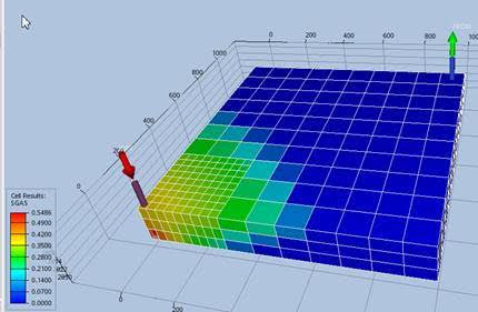
Here is an example of a visualisation of a model with local grid refinement:
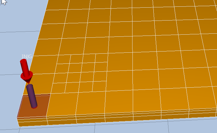
Here is an example of setting up a simple LGR with the following keywords in the file included as TYPE GRDECL:
carfin
 lgrxxx 2 3 2 3 1 1 4 4 2 /
endfin
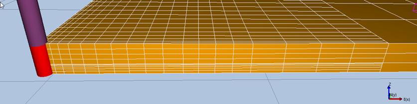
This will refine the domain from I=2 to I=3, J=2 to J=3, and K=1 by a factor of 2, into a 4 by 4 by 2 local grid, which should appear on the output as:
HXFIN, HYFIN, HZFIN
Specify the relative sizes of the refinement cells in X, Y and Z directions within a LGR data block. HXFIN, HYFIN and HZFIN expect a number of entries equal to the number of refinement cells in X, Y and Z directions in the LGR block, with each entry being the ratio between the cell size and the previous cell size (I-1, J-1, K-1), in a given global cell. Note that the number of cells and indices (I,J,K) being referred to, are those relative to the specific LGR block, not the global ones.
Default values specified by the special asterisk character (e.g. 2*) are given a value equal to 1, which means no size change with respect to the previous cell.
HXFIN, HYFIN and HZFIN are normally used in conjunction with NXFIN, NYFIN and NZFIN. See example below:
CARFIN
XXX 1 5 1 5 1 3 20 20 10

NXFIN
8 4 4 2 2 /

NYFIN
8 4 4 2 2 /

NZFIN
2 2 6 /

HXFIN
1 2 3 4 5 6 7 8 9 10 11 12 13 14 15 16 17 18 19 20 /

HYFIN
1 2 3 4 5 6 7 8 9 10 11 12 13 14 15 16 17 18 19 20 /

HZFIN
2* 2* 1 2 3 4 5 6 /

ENDFIN
NXFIN, NYFIN, NZFIN
Specify how the refined cells are to be split between global cells. So for NXFIN with ixu-ixl+1=4, four global cells refined in x-direction expect 4 arguments, the arguments sum to nxref, the refinement dimension.
EQLNUM
Specify the EQUILIBRATION data to be used for each cell.
\(N_x N_y N_z\) integer values are expected, which should each be in the range 1 to Neq, where Neq is the number of EQUILIBRATION data blocks provided in the input. The order of values is the GRDECL default natural order.
EQLNUM associates each cell to an EQUILIBRATION data set, with the EQLNUM integer indices referring to the order in which EQUILIBRATION data sets are found in the input. That is, an EQLNUM value of 1 associates the cell with the first EQUILIBRATION block, 2 with the second and so on.
GDFILE
It allows to read an Eclipse grid in .EGRID format. See example below:
GDFILE
base.EGRID  /
GDFILE is followed by a new line containing the grid file name. The card must be terminated by a forward slash.
The filename may be enclosed with quotes:
GDFILE
"base.EGRID"  /
Note that when using an absolute path for the filename, then quotes are mandatory, for example:
GDFILE
"/home/me/grid_fikes/base.EGRID"  /
FIPNUM, FIPXXX
FIP arrays are needed to compute fluid in place, flow rates and totals by region, and inter regions flows, which are all reported to the summary file.
Multiple FIP arrays can be defined (currently up to 6), and each of them divides the reservoir in regions, labelling each region with an integer, and assigning to each grid block the region number it belongs to. If only one partitioning by regions is required, the standard FIPNUM array can be used. FIPNUM expects
\(N_x N_y N_z\) integer values, which should each be in the range \(1\) to \(N_{reg}\), where \(N_{reg}\) is the number of
regions introduced by FIPNUM. The order of values is the GRDECL default natural order. An example is
given below:
FIPNUM
500*1 500*2 /
In this example the first 500 grid blocks are assigned to region number 1, the remaining 500 grid blocks
are assigned to region 2.
If more than one partitioning by region is needed, the user defines the FIP arrays names, adding arbitrary
letters to the FIP prefix. A name with 8 or fewer characters is recommended, to retain compatibility with
the Eclipse output mnemonics. An example using the EQUALS operator to define FIPXXX is given
below:
EQUALS
FIPXXX 1 1 15 4* /
FIPXXX 2 16 30 4* /
/
In this example ‘XXX’ is added to FIP to define the FIPXXX array, and EQUALS is used to define
region 1 as the first half of the domain in the I-direction, and region 2 as the second half.
The use of FIP arrays will add region reports to the summary file, see Line Graphic Mnemonic,
and will output also the FIP arrays to the static properties associated with the grid.
NNC
It specifies one or more non-neighbour connections, beyond those already generated internally for faults. Each user-defined connection between two non-neighbours cells requires the specification of the (I,J,K) logical coordinates of the two grid blocks being connected, followed by a transmissibility value. Each connection must be defined in a new line terminated by a slash, and a NNC data block is terminated by a line containing only a forward slash. More NNC data blocks can be specified for the same GRDECL grid.
The transmissibility units are cP.m3/day/bar.
See below an example defining two non-neighbour connections:
NNC
1 1 1  1 1 3 32.5 /
1 1 1  2 1 3 45.1 /
/
FILEUNIT
This keyword is read and ignored. It allows the user to write the units that have been used in a particular file. To impose a unit system either FIELD or METRIC should be used instead.
ECHO, NOECHO, INIT, EDIT, REGIONS
These keywords are available to accommodate the combinate of several Eclipse section keywords into a single grdecl Eclipse input file. However, no action is performed when read.