WELL_DATA
The WELL_DATA block is used to set up a production or injection well in the model. WELL_DATA wells can be given several targets in terms of bottom hole pressure, surface volume flow rates or mass flow rates, and the well will automatically switch to the most restrictive mode when it is solved.
Below an example of a well definition:
WELL_DATA injg
  CIJK_D   25 1 50 55
  DIAMETER 0.1524 m
  WELL_TYPE GAS_INJECTOR
  INJECTION_ENTHALPY_P  120 Bar
  INJECTION_ENTHALPY_T  45 C
  BHPL     400    Bar
  SHUT
  DATE 1 JAN 2025
  OPEN
  TARG_GM 1.0 Mt/y
  DATE 1 JAN 2045
  SHUT
END
The instructions above define an injector initially shut, which starts injecting 1 Mt of gas in Jan 2025. Injection continues until Jan 2045 when the well is shut again. The energy of the fluid being injected is defined specifying a pressure and a temperature.
The options and setting supported by WELL_DATA are listed below:
WELL_TYPE
Defines the type of wells. Options are:
PRODUCER (This implies a multi-phase producer)
OIL_INJECTOR
GAS_INJECTOR
WATER_INJECTOR
SOLVENT_INJECTOR
Rate Target Options
Different targets can be given, these are grouped by type below.
For surface volume rate targets the options are:
TARG_OSV: Oil surface volume rate
TARG_GSV: Gas surface volume rate
TARG_WSV: Water surface volume rate
TARG_SSV: Solvent surface volume rate
TARG_LSV: Liquid (sum of oil and water) surface volume rate
For mass rate targets the options are:
TARG_OM: Oil mass rate
TARG_GM: Gas mass rate
TARG_WM: Water mass rate
TARG_SM: Solvent mass rate
- Other targets:
TARG_RV: Well reservoir volume target
The liquid target only applies to a producer.
USE_HIST_TARG
Historical data can be used to specify the target for a well. When using historical data as well target only one target can be specified per well. The target is imposed in the WELL_DATA section using the keyword USE_HIST_TARG followed by the target, which can be one of the following:
Target |
Target |
||
|---|---|---|---|
O |
Oil volume rate at surface conditions |
OM |
Oil mass rate |
G |
Gas volume rate at surface conditions |
GM |
Gas mass rate |
W |
Water volume rate at surface conditions |
WM |
Water mass rate |
S |
Solvent volume rate at surface conditions |
SM |
Solvent mass rate |
L |
Liquid volume rate at surface conditions |
BHP |
Bottom hole pressure |
Note: a suffix SV (Surface Volume) can be added to the volume rate targets, e.g. target OSV is the same as O.
Example of using a historical target of gas mass rate for a production well:
WELL_DATA well1
  WELL_TYPE PRODUCER
  CIJK 10 10 1 1
  USE_HIST_TARG GM
END
Wells controlled using historical data are treated differently to normal wells in the following way:
Observed rates and BHP are written to the summary file. (The mnemonic has a H added at the end).
Wells can only have one control model (other observed data is just reported). Available control modes are RATE and BHP.
For an injector well controlled by rate, the BHP limit is set to a very high value automatically to reduce the possibility of the well changing to BHP control.
For a producer well controlled by rate, the BHP limit is set to a very low value automatically to reduce the possibility of the well changing to BHP control.
When using this type of target, the corresponding historical data must be provided. See HISTORY_DATA.
CIJK_D
This keyword takes four compulsory arguments: I, J, KL, and KU. It requests the creation of a set of well completions in the column of cells from cell I,J,KL to cell I,J,KU.
CIJK_D <I> <J> <KL> <KU>
CIJK_D counts K-indices from the top of the reservoir downwards.
<I> = I-location of the set of well completions (GRDECL grid format)
<J> = J-location of the set of well completions (GRDECL grid format)
<KL> = K-Lower index (from the top) of the set of well completions (GRDECL grid format)
<KU> = K-Upper index (from the top) of the set of well completions (GRDECL grid format)
More than one CIJK_D keyword can be entered, to specify completions in different columns.
See example below:
CIJK_D      15  50    31  36
CIJK_D      15  51    37  40
Additional arguments can be added for each set of completions to specify the drilling direction and the completion connection factor (CCF). For the drilling direction the options are:
X (alias DIR_X)
Y (alias DIR_Y)
Z (alias DIR_Z)
For example to specify an horizontal well with two completions in the Y direction:
CIJK_D  15  50  36   36   Y
CIJK_D  15  51  36   36   Y
If the drilling direction is not specified, it will default to Z.
The user can also manually introduce the CCF or Well transmissibility factor. CCF is normally computed internally, using the radius, the connection’s effective Kh and the skin factor. However, the CCF can be introduced by the user and avoid the internal computation. This is done adding the following extra parameters:
CCFUSER = Keyword specifying that the CCF is going to be provided by the user for this completion
<Value> = Numerical value of the CCF
<Units> = Unit system of the value introduced. This can be one of the following: 1) FIELD (bbl.cp/d/psi), 2) METRIC (m^3.cp/d/bar) or 3) SI (m^3)
For example to specify a CCF manually we would do:
CIJK_D  15  50  36   36   Y   CCFUSER   3.0     METRIC
CIJK_D  15  51  36   36   Y   CCFUSER   1.301   FIELD
Note that we had to include the drilling direction, this is also true when using the default Z direction.
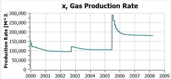
The CIJK_D keywords may be placed after TIME or DATE. New completions will become active from the TIME at which they are defined. So entering data like:
TARG_OSV 32000 m^3/day
CIJK_D 10 10  3  3
TIME 1000 d
CIJK_D 10 10  2  2
TIME 2000 d
CIJK_D 10 10  1  1
will produce results in which the effect of the extra completions on the gas production rate can be seen, as shown below:
For PFLOTRAN advanced users, a CIJK card (or its alias CIJK_Z) is also available, for which the K-index counts upwards from the bottom of the reservoir.
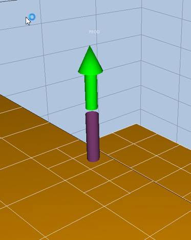
CIJKL_D
Request a well completion in a local refinement. Form is similar to CIJK_D for normal completions, but extra local grid name.
For example:
CIJKL_D 3 3 1 1 XXX
Arguments are ix, iy, izl, izu, the well being completed in cells from (ix,iy,izl) to (ux,iy,izu) in refinement name XXX. The CIJKL and CIJKL_Z variants expect the iz indices to be layers counting from the bottom of the grid, the CIJKL_D expects values counting from the top of the grid.
Hereis an example of a visualisation of such a completion:
OPEN
When a well is defined, it is normally opened. However, SHUT may be used to shut the well, and it will then remain shut until a subsequent OPEN keyword is processed.
SHUT
SHUT a well. This effectively removes it from the simulation until an OPEN is encountered.
RADIUS
The radius of the well. Currently only a single value per well is supported. Note that a unit is required.
An example is:
RADIUS 0.0762 m
If not enter the radius default to 0.1524 m.
The effect of the radius upon the completion connection factor (CCF) calculated for the well is detailed in the Theory Manual in the Well Model section.
DIAMETER
The diameter of the well. Currently only a single value per well is supported. Note that a unit is required.
An example is:
DIAMETER 0.05 m
If not entered the diameter defaults to 0.3048 m.
The effect of the diameter upon the completion connection factor (CCF) calculated for the well is detailed in the Theory Manual in the Well Model section.
SKIN_FACTOR
The skin factor for the well. The default is no skin. Currently only a single value per well is supported. An example is:
SKIN_FACTOR 0.1
The effect of the skin factor upon the completion connection factor (CCF) calculated for the well is detailed in the Theory Manual in the Well Model section.
EFFECTIVE_KH
Defines the connection’s effective \(K_h\) (permeability x thickness). If defaulted is computed internally using the grid block data. If a value > 0 is found, and CCF is defaulted, this quantity is used to compute the CCF, ignored otherwise. The \(K_h\) accepted units are: mD.m or mD.ft. Currently only a single value per well is supported. An example is:
EFFECTIVE_KH 3000 mD.m
The effect of the connection’s effective \(K_h\) upon the completion connection factor (CCF) calculated for the well is detailed in the Theory Manual in the Well Model section.
PRESSURE_RADIUS_R0
Pressure equivalent radius \(r_0\), which is used to compute the CCF if CCF is defaulted, ignored otherwise. If a value > 0 is not found, it is computed internally using the grid block data. Note that distance units are required, e.g. m, ft, … Currently only a single value per well is supported. An example is:
PRESSURE_RADIUS_R0 50 m
The effect of the pressure equivalent radius \(r_0\) upon the completion connection factor (CCF) calculated for the well is detailed in the Theory Manual in the Well Model section.
CONST_DRILL_DIR
Defines the drilling direction for the entire well, if this changes by completion, specify this direction in CIJK_D.
The default drilling direction is in the Z vertical direction. The options available with this keyword are DIR_X, DIR_Y and DIR_Z, with the default being DIR_Z. Alternatively X can be used instead of DIR_X, Y instead of DIR_Y, and Z instead of DIR_Z.
The effect of the drilling direction upon the completion connection factor (CCF) calculated for the well is detailed in the Theory Manual in the Well Model section.
BHPL
The bhp limit. This is a minimum bhp for a producer and a maximum bhp for an injector. Note that the units are specified. An example is:
BHPL 689.4757 Bar
D_REF
This over-rides the default BHP reference depth, which is the depth of the shallowest completion. Units are required.
Z_REF
This over-rides the default BHP reference depth, which is the depth of the shallowest completion. This is similar to D_REF, but is specified as an elevation rather than a depth. So a reference depth of 3000 meters would be entered as 3000 m with D_REF, but -3000 m with Z_REF. Units are required.
INJECTION_ENTHALPY_P
This specifies the pressure used to calculate the specific enthalpy of the injected fluid. Units are required. Needed only for thermal problems.
INJECTION_ENTHALPY_T
This specifies the temperature used to calculate the specific enthalpy of the injected fluid. Units are required. Needed only for thermal problems.
DATE
This specifies the date at which following well settings become effective. Example:
DATE 1 JAN 1993
The use of DATE is discussed in scheduling well operations.
TIME
This specifies the time at which following well settings become effective. An examples is:
TIME 2 y
Units are required. The use of TIME is discussed in scheduling well operations.
ZINJ
It applies to COMP EOS runs only.
It specifies the composition of the injected phase in mole percentage (PERCENT) or fraction (FRAC). For example for COMP 7 EOS (6 Hydrocarbons):
ZINJ PERCENT 77 20 3 0 0 0
MULT_PI
Allows all the completion connection factors to be multiplied by a factor.
GC_WEIGHT
Set the weight for this well in the group control. Default is the sum of the well completion connection factors.
Users are strongly advised not to mix default values and set values in a group.
Scheduling well operations
There must be only one WELL_DATA block for each well. Within the WELL_DATA block a series of well operations may be defined. It is possible to set the time in the run schedule at which these operations occur. An example is:
WELL_DATA injg

  RADIUS 0.0762 m
  CIJK_D 1 1 1 1
  WELL_TYPE SOLVENT_INJECTOR
  BHPL
  689.4757 Bar
  SHUT

  TIME 2 y
  OPEN
  WELL_TYPE WATER_INJECTOR
  TARG_WSV 1907 m^3/day

  TIME 3 y
  WELL_TYPE SOLVENT_INJECTOR
  TARG_SSV 339802 m^3/day

END
In this case a well called ‘injg’ is completed in the top corner cell (1,1,1). A bhp limit is set, but rather than start operating immediately, the well is shut. The well remains shut for 2 years, and then is opened as a water injector. At 3 years the well is converted into a solvent injector. This is the first part of a water alternating gas injection sequence.