SIMULATION
Defines the flow model to simulate. See below an example to define a GAS_WATER case running in isothermal mode:
SIMULATION
  PROCESS_MODELS
    SUBSURFACE_FLOW Flow
      MODE GAS_WATER
      OPTIONS
        ISOTHERMAL
        RESERVOIR_DEFAULTS
      /                    ! end options
    /                      ! end subsurface_flow
  /                        ! end process_models
/                          ! end simulation
Here is an unlikely example showing almost every one of the keywords which will be described below:
SIMULATION
  PREAMBLE
  ABOUT
  PROCESS_MODELS
    SUBSURFACE_FLOW Flow
      MODE GAS_WATER
      OPTIONS
        ISOTHERMAL
        RESERVOIR_DEFAULTS
        NOGASSOL
        ANALYTICAL_JACOBIAN
        HYSTERESIS
        HYSTERESIS_PC 0.1
        TL_OMEGA 0.5
        COMP_DEP_SFNS
        STRAND
        EWBD
      /                        ! end options
    /                          ! end subsurface_flow
  /                            ! end process_models
  CHECKPOINT
    [checkpoint block]
  /                            ! end checkpoint
  restart test-23.0000y.h5
  ERESTART base 3000 d
/                              ! end simulation
Below is a list of all options that can be specified in the SIMULATION block:
MODE
The MODE keyword selects the flow model for the simulation, and can take the following arguments: COMP, COMP3, COMP4, BLACK_OIL, GAS_WATER, TOIL_IMS, TODD_LONGSTAFF, SOLVENT_TL. MODE must be entered by the user as it cannot be defaulted.
For COMP mode, one must enter:
MODE COMP [Nc] EOS
where Nc is the total number of components (including water), for example:
MODE COMP 2 EOS
for two components, one of which is water.
COMP3 and COMP4 are two different modelling options of the same multigas component formulation. COMP3 models three components: GAS, SOLVENT and WATER. COMP4 models 4 components: OIL, GAS, SOLVENT and WATER. In both options the SOLVENT and GAS components share the gas phase, both may dissolve in the oil, and the solvent component may dissolve in the aqueous phase.
The degree of solution of the solvent component in the oil is defined by the table PVCOS, which follows the pattern of the PVCO table.
The PVT properties for the solvent may be specified explicitly using PVDS, or obtained from a property database (currently this is always CO2 properties generated using the Span-Wagner equation). In most respects the multi-gas model follows the existing solvent model – for example to inject the solvent component:
WELL_TYPE SOLVENT_INJECTOR
BHPL     400    Bar
TARG_SSV 2831684 m^3/day
ISOTHERMAL
Goes in the OPTIONS block of SIMULATION. If present, the model will run as isothermal, maintaining the same temperature as given in the initialization. All flow models run with the thermal option as default, except for COMP, which must run with ISOTHERMAL.
NOSLVSOL
Goes in the OPTIONS block of SIMULATION. It is valid only for COMP3 and COMP4 modes: if present turns off the the solution of solvent in the aqueous phase.
NOGASSOL
Goes in the OPTIONS block of SIMULATION. See the following example:
SIMULATION
  SIMULATION_TYPE SUBSURFACE
  PROCESS_MODELS
    SUBSURFACE_FLOW Flow
      MODE GAS_WATER
      OPTIONS
        RESERVOIR_DEFAULTS
        ISOTHERMAL
        NOGASSOL
      /                        ! end options
    /                          ! end subsurface_flow
  /                            ! end process_models
/                              ! end simulation
This is valid only for the GAS_WATER module: if present turns off the the solution of gas in the aqueous phase.
RESERVOIR_DEFAULTS
Goes in the OPTIONS block of SIMULATION.
If present causes PFLOTRAN to automatically set some values that are commonly useful for simulating reservoir models. It is possible to use RESERVOIR_DEFAULTS and still override any of the selected defaults by using the appropriate keyword in the corresponding card. A message will be output warning that a RESERVOIR_DEFAULTS default has been overridden in this way.
The values set by RESERVOIR_DEFAULTS are listed in reservoir defaults values.
ANALYTICAL_JACOBIAN
Goes in the OPTIONS block of SIMULATION.
If present, causes the derivatives in the Jacobian matrix to be computed analytically instead of approximated. Leads to better convergence of the nonlinear solver in most cases.
Note that this option is automatically selected as part of RESERVOIR_DEFAULTS.
HYSTERESIS
Goes in the OPTIONS block of SIMULATION. See the following example:
SIMULATION
  SIMULATION_TYPE SUBSURFACE
  PROCESS_MODELS
    SUBSURFACE_FLOW Flow
      MODE GAS_WATER
      OPTIONS
        RESERVOIR_DEFAULTS
        ISOTHERMAL
        HYSTERESIS
      /                      ! end options
    /                        ! end subsurface_flow
  /                          ! end process_models
END                          ! end simulation
Activate the relative permeability hysteresis modelling in the simulation using the Carlson model [C+81]. The user must supply the indices of the required CHARACTERISTIC_CURVES sections to be used for the imbibition process using the IMBNUM grid keyword.
HYSTERESIS is available for the GAS_WATER, COMP3, COMP4 and COMP modes. If data is supplied, GAS_WATER can model relative permeability hysteresis of both wetting and non-wetting phases. Instead COMP3, COMP4 and COMP can only model relative permeability hysteresis of the gas phase.
When using this option new fields will be output in the restart file. Following the notation from Residual Trapping and Stranded Gas Saturation these are:
SPNMAX |
(\(S_{g, \mbox{max}}\)) Maximum saturation of the non-wetting phase (gas) before changing from imbibition to drainage |
SPNTRAP |
(\(S_{g,\mbox{trap}}\)) Maximum potential trapped saturation for the non-wetting phase (gas) |
SPNSHFT |
Saturation shift for the relative permeability of the non-wetting phase |
SPWSHFT |
Saturation shift for the relative permeability of the wetting phase |
SGSTRAND |
(\(S_{g,\mbox{strand}}\)) Actual trapped saturation of the non-wetting phase (gas) (Optional with keyword STRAND) |
HYSTERESIS_PC, EHYST
Goes in the OPTIONS block of SIMULATION.
HYSTERESIS_PC specifies the curvature parameter for capillary pressure hysteresis, [Kil76]. It takes a number as argument, which must be greater than zero. See example below:
HYSTERESIS_PC 0.1
When HYSTERESIS_PC is entered both the capillary pressure and relative permeability hysteresis are active. The user must supply the indices of the required CHARACTERISTIC_CURVES sections to be used for the imbibition process using the IMBNUM grid keyword.
This option is only available for the GAS_WATER mode.
RESTART
Goes in the SIMULATION block of SIMULATION.
RESTART specifies the file that contains a previous state of the simulation in PFLOTRAN format, from which the simulation can be restarted. It takes a file name as argument. For more details see RESTART. An example is given below:
SIMULATION
  [process models etc blocks]
  RESTART restart_file.h5
/
If not specified, the simulation starts from its initial state.
ERESTART
Goes in the SIMULATION block of SIMULATION.
ERESTART specifies the file that contains a previous state of the simulation in Eclipse format restart file, from which the simulation can be restarted. Takes as an argument a file name. For more detail see ERESTART. An example is given below:
SIMULATION
  [process models etc blocks]
  ERESTART base 3000 d
/                                      ! end simulation
If not specified, the simulation starts from its initial state.
CHECKPOINT
Goes in the SIMULATION block of SIMULATION.
Define instructions to save the simulation states for a given set of times. For more details see CHECKPOINT. An example is given below:
SIMULATION
  [process models etc blocks]
  CHECKPOINT
     FORMAT HDF5
     PERIODIC TIMESTEP 20
  /                          ! end checkpoint
/                            ! end simulation
TL_OMEGA
Goes in the OPTIONS block of SIMULATION.
Only required for the TODD_LONGSTAFF and SOLVENT_TL modes.
Takes one argument, which specifies the Todd-Longstaff model omega value, which may lie between 0 and 1. The default value is 0. An example is given below:
SIMULATION
  SUBSURFACE_FLOW Flow
    MODE  TODD_LONGSTAFF
    OPTIONS
      ISOTHERMAL
      RESERVOIR_DEFAULTS
      TL_OMEGA 0.5
    /                      ! end options
  /                        ! end subsurface_flow
/                          ! end simulation
COMP_DEP_SFNS
This option, only available in the COMP3 compositional mode, allows the water/gas relative permeability and capillary pressure functions to become a function of the gas phase composition. In COMP3 there are three components (water, gas, solvent) split over two phases (water and gas). The gas component is usually mainly methane and the solvent component is usually CO2.
If COMP_DEP_SFNS is used, the user will be expected to provide relative permeability and capillary pressure functions for both the gas/water and solvent/water systems. The gas/water system values are provided by the usual SGFN and SWFN functions. In addition, the solvent/water system values are defined by the SWSFN and SGSFN tables, for example:
TABLE swsfn_table
  PRESSURE_UNITS Pa
  SWSFN
    0.2 0 3.1026
    0.25 0.0 1.3120
    1.0 1.0 0.0
  /
END

TABLE sgsfn_table
  SGSFN
    0.0 0.0
    0.05 0.0
    0.8 1.0
  /
END
The values from the SGFN/SWFN and the SGSFN/SWSFN table lookups are mixed as a function of the mole fractions of the gas and solvent components in the vapour phase.
STRAND
Goes in the OPTIONS block of SIMULATION.
By including the STRAND keyword in the simulation option, the simulator will output the cumulative stranded mass gas, also known as residual saturation. The STRAND option is only supported for the GAS_WATER solution mode. See example below:
SIMULATION
  SIMULATION_TYPE SUBSURFACE
  PROCESS_MODELS
    SUBSURFACE_FLOW Flow
      MODE GAS_WATER
      OPTIONS
        RESERVOIR_DEFAULTS
        ISOTHERMAL
        STRAND
      /
    /
  /
END
This option causes the output of the field total stranded and unstranded gas masses (FGMST and FGMUS) to the summary file (see line graph mnemonics), and will also print the FGMST and FGMUS partitioning in the .out file, at the same time restart files are written:
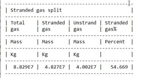
Note that FGMST and FGMUS add up to FGMGP ( Field Gas Mass in the Gas Phase). For more details on how FGMST is computed, see Residual Trapping and Stranded Gas Saturation.
ABOUT
Goes in the SIMULATION block of SIMULATION.
For advanced users or debugging purposes only.
Causes additional information about PFLOTRAN_OGS to be written to the .out file, under the heading PROVENANCE.
The time and date of compilation and the current PFLOTRAN_OGS Git commit can always be found in this section. When the keyword ABOUT is included, much more detailed information about the compilation and version control is included.
PREAMBLE
Goes in the SIMULATION block of SIMULATION.
Causes some additional information about the run setup to be output to the screen before the run starts. This information can also be found in the run’s .out file by default.
FLOWS
Instructs the simulator to store and report fluxes in the I, J and K directions for each phase, which are output for each grid block to the restart file (e.g. for water, FLOWI+, FLOWJ+, FLOWK+).
The units of the restart file output arrays starting with FLO (FLOOILI+, … FLOWGASK+) are surface volume per day, sm^3/d.
SATDEN
Goes in the OPTIONS block of SIMULATION.
When the flow rate is calculated between two cells with different depths, a fluid density is required for each phase to correct for the hydrostatic head between the cells. The default is to use a simple density average. With SATDEN, a saturation weighted average is used instead. To use this option, insert the SATDEN keyword in the simulation option block, for example:
SIMULATION
  SIMULATION_TYPE SUBSURFACE
  PROCESS_MODELS
    SUBSURFACE_FLOW Flow
      MODE COMP3
      OPTIONS
        RESERVOIR_DEFAULTS
        ISOTHERMAL
        SATDEN
      /
    /
  /
END
MISCIBLE
Goes in the OPTIONS block of SIMULATION, and it is used only for COMP mode runs, i.e. when a multicomponent Equation of State characterises the multiphase system, and ignored in any other case. The MISCIBLE treatment is required for equation of state modelling when approaching the critical point or for miscible floods (such as when CO2 invades hydrocarbon regions). For more details see Miscible treatment in the theory section. An example on how to request the miscible treatment is given below:
SIMULATION
  SIMULATION_TYPE SUBSURFACE
  PROCESS_MODELS
    SUBSURFACE_FLOW Flow
      MODE GAS_WATER
      OPTIONS
        RESERVOIR_DEFAULTS
        ISOTHERMAL
        MISCIBLE
      /
    /
  /
END
When the MISCIBLE option is used, PARACHOR values are required by the simulator in COMP EOS.
LOCAL_DIAGONAL_TENSOR
By including this keyword in the OPTION block, the user activates the computation of transmissibilities using the local diagonal tensor, overwriting the default use of the global coordinate system (x,y,z) when projecting Kx, Ky and Kz. This option is available only for model using grdecl grids.
EWBD
By including this keyword in the OPTION block, the user activates the use of an Explicit WellBore Discretisation for the wells. This option makes the well model more robust in exchange on some accuracy. Consider this option if having many well warnings in your simulation.